31. Circuit method of switching power supply (AC-DC converter)
Integral switching power supply for electronic device. Once there used a linear power supply in which the transformer rolled with the coil in the core was used, since it was extremely heavy and the conversion efficiency was remarkably low therefore recently switching power supplies is widely used. There are various type of switching power supply units by toology and circuit method. Since those are different by cost, size and efficiency, select suitable one to meet for system design requirement.
| Circuit method | Characteristic | Circuit diagram |
|---|---|---|
|
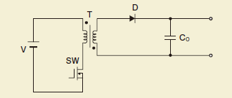
Flyback method |
Circuit method to storing the electric power in the inductor during the period when switching element is on, and output during the electric power off period. It is used in the small capacity model, and unsuitable for the larger model of output power capacity. There is demerit of flowing a comparatively huge peak current to the switching element and the inductor though there is merit that wider input voltage range can be secured. The RCC(Ringing Choke Converter) method is a type of Flyback method. |
|
|
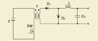
Forward method |
Circuit method to let transmit the electric power from the primary side to the secondary side during the period when switching element is on. It is adopted in many switching power supplies because the circuit architecture is simple, and can achieve stable control. It is also used in the comparatively large model, and certainly used in smaller power output electric power capacity. There is weakness for too much noise generation of the MHz belt though it can achieve high power conversion efficiency. |
|
|
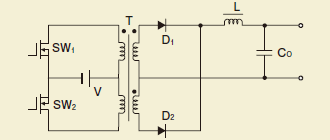
Push-pull method |
Circuit method using two transformers alternately by using two switching elements. The output electric power capacity is applicable in a comparatively large model because the utilization efficiency of the transformer rises. However, it is necessary to note the biased magnetization of transformer. |
|
|
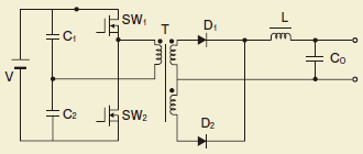
Half-bridge method |
The circuit operation is same as the push-pull method, there is merit for using low withstand pressure in switching element because the voltage impress to the transformer is lower by half of the input voltage. It is being used in upto 1kW model and applicable for the model of larger output electric power capacity. |
|
|
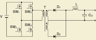
Full bridge method |
Circuit method that changed the input part of half bridge method to full bridge. There is merit for using switching element of low withstand pressure similar to the half-bridge method, although there is demerit of complex circuit architecture, control compared to the half-bridge method. Can obtain a high power conversion efficiency. It can be applicable to the power supply where the output power capacity is high. |
|

