36. Fundamental combilation logic device
Various complex logical circuits can be composed by combining AND (logical product), OR (logical add), and NOT (logical inverse). Here, it explains about the circuit operation, schematic diagram, and the truth table about Adder (Adding machine) and three state buffer.
| Logic circuit | Explanation | Circuit diagram | Truth table | |
|---|---|---|---|---|
|
Adder |
Half adder |
It is a logical circuit in which the same digit of two binary numbers such as input A and input B, is operated, the operation result of the digit is output by “Output (S,Sum)”, and carry is output by “Carry output (C,Carry out)”. It can be composed of three types of logical circuits of AND, OR, and NOT. |
Input A、Input B、Output S、Sum、Carry outC、Carry out |
|
|
Full adder |
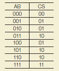
It is a logical circuit that operates the same digits other than the least significant of two binary numbers such as input A and input B, afterwards executes the operation with carrying input X from the subordinate position, and outputs the result “Output (S,Sum)”. The addition of binary numbers of an arbitrary digit number can be achieved by connecting carrying output C of the subordinate position with carrying input X of the upper position. One Full adder is composed of 2 Half adder and one OR. |
Input A, input B, carrying input X, output (S,Sum), and carrying output (C,Carry out) |
|
|
|
Three-State Buffer |
Three-State |
The output circuit that can set by using gate input G when the output Y is in high impedance (floating) state is called “Three state”. It can be switched such that the input signal X will be output as it is by gate input G or the output is set in the high impedance state. |
Input X, gate input G, and output Y |
|
Two-way buffer |
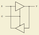
It is a circuit that enables the direction of the data transmission to switch by combining 2 three state buffers. The data propagates from Y to X direction when gate input G is low (L), and it propagates from X to Y direction when the gate input G is high (H). |
Input (output) X, gate input G, output (input) Y
|
|
|


