37. Basic sequential circuit: Flipflop
Flipflop (Flip-Flop) is a logical circuit that can maintain (memory) information of 1 bit. It is composed of two switch elements that operate complementarily, and maintains the former state as long as there is no input. There are various circuit composition in the flipflop. It explains the RS flipflop, JK flip-flop, D flipflop, and T flipflop as follows.
| Basic sequential circuit | Explanation | Circuit diagram | Truth table |
|---|---|---|---|
|
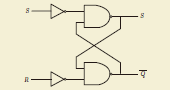
RS Flip flop |
It is the most basic Flip flop. Output Q is set in “High (H)” when input S(set) is “High (H)”. Output Q switches into “Low (L)” when input R(reset) is considered “High (H)” while the output Q is in “High (H)” state. |
|
|
|
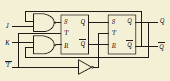
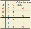
JK Flip flop |
JK Flip flop can set the 2 input simultaneously in “High (H)”. This point is is different from the RS Flip flop. Output Q becomes “High (H)” when the only input J is “High (H)” for the valid edge (Rise or fall of signal) clock signals to be input in trigger terminal T. Output Q reverses when inputting the input J and input K simultaneously. |
|
|
|
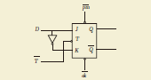
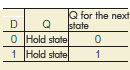
D Flip flop |
It is a circuit where the value of input D is certainly maintained in the edge (Rise or fall of the signal) of clock signals to be input in the trigger terminal T. |
|
|
|
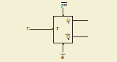
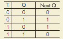
T Flip flop |
It is the summarization for the input J and input K of JK Flip flop. Output Q reverses whenever clock signals are input to trigger terminal T. |
|
|