44. Behaviors of Thyristors/Triacs
Both are the rectifying devices for the electric power control
usage.
Triac is a bi-direction controlled device while
thyristor is a single
direction controlled.
Fundamental behaiviour of thyristor
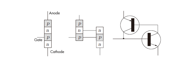
Thyristor (Thyristor) is a semiconductor rectification element of three terminals that can conduct between anode (A) and cathode (K) by draining the gate current from gate (G) into cathode (K). It is called SCR(Silicon Controlled Rectifier). The structure adopted is the pnpn structure that laminated the semiconductor in the order of p type, n type, p type, and n type. The element that draws out the gate terminal from p type semiconductor is called p gate product, and the element that draws out the gate terminal from n type semiconductor is called n gate product. As a principle, it is equivalent to the multiple circuit that combined the pnp transistor with the npn transistor as shown in figure. Let’s see the detailed operation. The conduction continues as it is, when a specific current flows from the gate by conducting (turn on) between anode and cathode.It is necessary to lower the current between the anode and anode less than or equal to a constant value to stop (turn on) the conducting state.By keeping such characteristics once switching over to the conducting state it is being used as the necessity to maintain the conducting state until the transit current becomes zero (0).

Triac
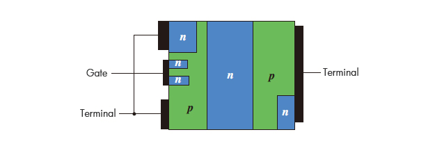
Although the thyristor is an element to achieve the OFF / ON control in one direction and it is the element that is the Triac(TRIAC) which improves this so and made possible the two-way OFF / ON control. Triac is an element that made to flow the electric current in two-way by anti-parallel connection of 2 thyristors. However, actually it is the monolithic structure as shown in figure but not simply composed of by connecting two thyristors.Further, Triac(TRIAC) is abbreviation of “Triode AC Switch” that is the product name when U.S. General Electric (General Electric) Co. sold in the market as pioneer in 1964.

Maximum rating of thyristor
| Terminology | Symbol | Unit | Explanation |
|---|---|---|---|
|
Peak repeat OFF voltage |
|
V |
The maximum voltage value repeated between A-K |
|
Peak repeat reverse voltage |
|
V |
The maximum reverse voltage value of repeated between A-K |
|
Non-repetitive peak off-state voltage |
|
V |
Non repetitive maximum voltage value between A-K |
|
Peak non repetitive reverse voltage |
|
V |
Non repetitive maximum reverse voltage value between A-K |
|
Average on current |
|
A |
Average ON current that can be continuously drawn |
|
RMS Forward Current |
|
A |
Continuously drawn RMS value of ON current |
|
Peak gate dissipation |
|
W |
Maximum momentary value of gate electricity consumption |
|
Mean gate power loss |
|
W |
Average value of tolerable gate power consumption |
Electrical characteristic of thyristor
| Terminology | Symbol | Unit | Explanation |
|---|---|---|---|
|
Peak gate forward voltage |
|
V |
Peak forward gate voltage between Gate and Cathode. |
|
Peak gate reverse voltage |
|
V |
Peak reverse gate voltage between G-K |
|
Peak gate forward current |
|
A |
Peak gate forward current between G-K |
Peak on voltage |
|
V |
The maximum value of voltage applied between A-K at ON status |
|
Gate trigger voltage |
|
V |
Minimum Gate voltage to turn ON |
|
Gate trigger current |
|
A |
Minimum Gate current to turn ON |
